ESP32 Touch Pad
Capacitive touch detection is possible on ESP32, ESP32-S2, ESP32-S3 and ESP32-P4 processors. In ESPHome, it is configured in two parts:
Component/Hub
Section titled “Component/Hub”The esp32_touch component creates a global hub enabling (capacitive) touch detection on GPIO pins
supported by ESP32, ESP32-S2, ESP32-S3 and ESP32-P4 processors. With this enabled,
binary sensors may then be configured to permit touch detection.
# Example configuration entryesp32_touch: setup_mode: falseConfiguration variables
Section titled “Configuration variables”-
setup_mode (Optional, boolean): Whether debug messages with the touch pad value should be displayed in the logs. Useful for finding out suitable thresholds for the binary sensors, but will spam the logs. See setting up touch pads for more information. Defaults to
false. -
id (Optional, ID): Manually specify the ID for code generation.
Advanced options
Section titled “Advanced options”These variables may be added to the hub component's configuration (above) and are useful for fine-tuning and/or when the sensors aren't behaving as expected.
All processors
Section titled “All processors”-
sleep_duration (Optional, Time): Set a time period denoting the amount of time the touch peripheral should sleep between measurements. This can decrease power usage but make the sensor slower. Default is about 27 milliseconds.
-
measurement_duration (Optional, Time): Set the conversion time for all touch pads. A longer conversion time means that more charge/discharge cycles of the touch pad can be performed, therefore increasing accuracy. Default is about 8ms, the maximum amount.
ESP32, ESP32-S2 and ESP32-S3 only
Section titled “ESP32, ESP32-S2 and ESP32-S3 only”-
low_voltage_reference (Optional): The low voltage reference to use for the charge cycles. One of
0.5V,0.6V,0.7V,0.8V. Default is0.5V. -
high_voltage_reference (Optional): The high voltage reference to use for the charge cycles. One of
2.4V,2.5V,2.6V,2.7V. Default is2.7V. -
voltage_attenuation (Optional, ESP32 only): The voltage attenuation to use for the charge cycles. One of
1.5V,1V,0.5V,0V. Default is0V.
For a more detailed explanation of the parameters above, please see the ESP-IDF documentation.
ESP32 only
Section titled “ESP32 only”- iir_filter (Optional, Time): Optionally set up an
Infinite Impulse Response
filter should be applied to all touch pads. This can increase the accuracy of the touch pads a lot, but higher values
decrease the response time. A good value to start with is
10ms. By default, the IIR filter is inactive.
ESP32-S2, ESP32-S3 and ESP32-P4 only
Section titled “ESP32-S2, ESP32-S3 and ESP32-P4 only”For each configuration category below, if one option is specified, all options must be specified. The configuration options below do not have any default values; in other words, they are inactive by default.
Filter configuration:
-
filter_mode (Optional): Sets the filter mode. Must be one of
IIR_4,IIR_8,IIR_16,IIR_32,IIR_64,IIR_128,IIR_256(S2/S3 only) orJITTER. -
debounce_count (Optional,
intrange 0-7): Sets the debounce count; if the measured values continue to exceed the threshold forn + 1times, the touch sensor state changes. -
noise_threshold (Optional,
intrange 0-3): Noise threshold coefficient. Higher = More noise resistance. The actual noise should be less than (noise coefficient * touch threshold). The coefficient is 0: 4/8; 1: 3/8; 2: 2/8; 3: 1. -
jitter_step (Optional,
intrange 0-15): Set jitter filter step size. -
smooth_mode (Optional): Level of filter applied on the original data against large noise interference. Must be one of
OFF,IIR_2,IIR_4orIIR_8.
For a more detailed explanation of the filter configuration, please see the ESP-IDF documentation.
Denoise configuration (ESP32-S2 and ESP32-S3 only, not available on ESP32-P4):
-
denoise_grade (Optional): Sets the denoise range of the denoise channel. Determined by measuring the noise amplitude of the denoise channel. Must be one of
BIT12,BIT10,BIT8orBIT4. -
denoise_cap_level (Optional): Select internal reference capacitance of denoise channel. Must be one of
L0,L1,L2,L3,L4,L5,L6orL7.
For a more detailed explanation of the denoise configuration, please see the ESP-IDF documentation.
Waterproof configuration:
-
waterproof_guard_ring (Optional, Pin): Sets the touch channel to use for the guard pad. The guard pad is used to detect the large area of water covering the touch panel.
-
waterproof_shield_driver (Optional): Shield channel drive capability configuration; the larger the parasitic capacitance on the shielding channel, the higher the drive capability needs to be set. Must be one of
L0,L1,L2,L3,L4,L5,L6orL7.
For a more detailed explanation of the waterproof configuration, please see the ESP-IDF documentation.
Binary Sensor
Section titled “Binary Sensor”The esp32_touch binary sensor platform lets you use the touch peripheral of the
ESP32 to detect if a certain pin is being "touched".
First, you need to setup the global touch hub. Then
you can add individual touch pads as binary sensors. When a touch is detected on these pins, the binary
sensor will report an ON state. And, of course, if no touch is detected, the binary sensor will report
an OFF state.

# Example configuration entryesp32_touch:
binary_sensor:  - platform: esp32_touch    name: "ESP32 Touch Pad"    pin: GPIOXX    threshold: 1000
Configuration variables
Section titled “Configuration variables”-
pin (Required, Pin): The pin to detect touch events on.
-
threshold (Required,
int): The threshold to use to detect touch events. See Finding Thresholds below for help determining this value. -
wakeup_threshold (Optional,
int): The threshold to use to detect touch events to wake-up from deep sleep. See Finding Thresholds below for help determining this value. Touch pad sensors that should trigger a wake-up from deep sleep must specify this value. The Deep Sleep Component must also be configured to enable wake-up from a touch event. Note that no filter(s) is/are active during deep sleep. -
All other options from Binary Sensor.
Raw Values
Section titled “Raw Values”If access to the raw values is required, a template sensor can be created that polls for them:
# Example configuration entry for accessing raw valuesesp32_touch:  id: esp32_touch_1
binary_sensor:  - platform: esp32_touch    id: esp32_touch_pad    pin: GPIOXX    threshold: 0
sensor:  - platform: template    name: "Raw touch value"    lambda: |-        return id(esp32_touch_pad).get_value();    update_interval: 3s
One example of use is a wide area pressure sensor that integrates a number of smaller sensors in an area. Make two strips of aluminium foil that sandwich paper, and connect one wire to a touch pin and the other to ground. Set up several sensors under a flexible object like a plastic mat, add the raw values, and apply a threshold.
Touch Pad Pins
Section titled “Touch Pad Pins”Various pins on the ESP32, ESP32-S2, ESP32-S3 and ESP32-P4 can be used to detect touches. They are as follows (using the default "raw" pin names/numbers):
| ESP32 | ESP32-S2 | ESP32-S3 | ESP32-P4 |
|---|---|---|---|
| GPIO4, GPIO0, GPIO2, GPIO15, GPIO13, GPIO12, GPIO14, GPIO27, GPIO33, GPIO32 | GPIO1 - GPIO14 | GPIO1 - GPIO14 | GPIO2 - GPIO15 |
Finding Thresholds
Section titled “Finding Thresholds”For each touch pad you want to monitor, you need to find a threshold value first. This threshold is used to determine if a pad is being touched or not using the raw values read from the processor's internal sensor hardware. When no contact is made with the sensor, the values will typically hover within a certain range; when the sensor's pad is touched, the value will change significantly, enabling the touch to be detected.
Exact values reported by the sensor hardware will vary based on the processor, PCB layout and potentially even environmental factors.
To find suitable threshold values, first configure the ESP32 touch hub to log measured
values using the setup_mode: configuration option. Next, add some binary sensors for the touch pads you want to
observe. You'll also need to put some (temporary) threshold values into the configuration (as shown below) to make the
validator happy; we'll replace these in a moment once we determine suitable values.
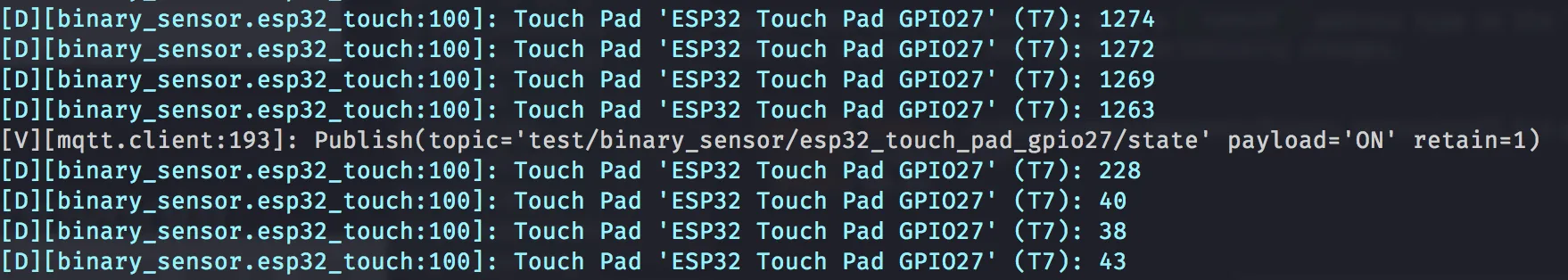
# Example configuration entry for finding threshold valuesesp32_touch:  setup_mode: true
binary_sensor:  - platform: esp32_touch    name: "ESP32 Touch Pad GPIO27"    pin: GPIO27    threshold: 1000
Upload the program/configuration and watch the device's logs; you'll see values being logged by the hub component. Touching the sensor's pins/pads should result in a (significant) change in the values being logged. Experiment with different amounts of force applied to the touch pad; a pattern should emerge, revealing a value that falls between "touched" and "not touched" which the binary sensor will then use to differentiate between the two states.
Once you've determined an appropriate value, update the threshold parameter in your configuration and test the updated configuration. You may need to repeat this process a few times to fine-tune the behavior and get it just right.
Finally, don't forget to disable the setup_mode option by setting it back to false ; leaving it enabled will
reduce the ESP's overall performance.
S2, S3 and P4 Variants
Section titled “S2, S3 and P4 Variants”NOTE
ESP32-S2, ESP32-S3 and ESP32-P4 Touch Configuration
The default measurement_duration and sleep_duration values are optimized for the original ESP32 and
may not work at all on S2/S3/P4 variants. These variants have different touch hardware requiring different timing settings.
Key differences:
- Touch values increase when touched (opposite of ESP32 which decreases)
- Higher raw values are returned compared to original ESP32
- Lower measurement duration required - the default 8ms is often too high for S2/S3/P4
Example settings for S2/S3/P4:
esp32_touch:  setup_mode: false  measurement_duration: 0.25ms  # Much lower than the 8ms default  sleep_duration: 0.5ms
binary_sensor:  - platform: esp32_touch    name: "Touch Sensor"    pin: GPIOXX    threshold: 1000  # Adjust based on your hardware
If you're familiar with the ESP32 hardware and pick up an S2, S3 or P4 variant, you're likely to notice some behavioral differences between them. In particular:
-
Raw touch sensor readings on the S2, S3 and P4 variants will generally return larger numeric values than the original ESP32 hardware.
-
Contact with the touch sensor on the S2, S3 and P4 variants will result in the raw sensor value reading increasing; on the original ESP32, contact would cause this value to decrease.
These behavioral differences are due to changes in the hardware and software (ESP-IDF) interfaces and should be expected -- if you are moving your configuration from an original ESP32 to an S2, S3 or P4 variant, expect that you'll need to make some adjustments to your configuration to accommodate this behavior.
Most importantly, the default measurement_duration of 8ms (optimized for original ESP32) is often too high for
S2/S3/P4 variants and can prevent touch detection from working entirely. Using a much lower value like 0.25ms has been
found to work across many S2/S3 devices, though specific parameters may still need tuning per hardware implementation.