Modbus Controller
The modbus_controller component creates a RS485 connection to either:
- control a Modbus server (slave) device, letting your ESPHome node to act as a Modbus client (master). You can access the coils, inputs, holding, read registers from your devices as sensors, switches, selects, numbers or various other ESPHome components and present them to your favorite Home Automation system. You can even write them as binary or float ouptputs from ESPHome.
- let your ESPHome node act as a Modbus server, allowing a ModBUS client to read data (like sensor values) from your ESPHome node.
To choose the role, set the role attribute of the Modbus upon which this modbus_controller component relies. client is the default.

Hardware setup
Section titled “Hardware setup”You need an RS485 transceiver module:
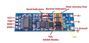
See How is this RS485 module working? on stackexchange for more details.
The transceiver connects to the UART of the MCU. For ESP32, pin 16 to TXD and pin 17 to RXD are the default ones but any other pins can be used as well. 3.3V to VCC and naturally GND to GND.
On the bus side, you need 120 Ohm termination resistors at the ends of the bus cable as per Modbus standard. Some transceivers have this already soldered onboard, while some slave devices may have them available via a jumper or a DIP switch.
NOTE
If you are using an ESP8266, serial logging may cause problems reading from UART. For best results, hardware serial is recommended. Software serial may not be able to read all received data if other components spend a lot of time in the loop().
For hardware serial only a limited set of pins can be used. Either tx_pin: GPIO1 and rx_pin: GPIO3 or tx_pin: GPIO15 and rx_pin: GPIO13.
The disadvantage of using the hardware UART is that you can’t use serial logging because the serial logs would be sent to the Modbus device(s) instead, causing errors.
Serial logging can be disabled by setting baud_rate: 0.
See Logger for more details
logger: level: <level> baud_rate: 0Configuration variables
Section titled “Configuration variables”-
modbus_id (Optional, ID): Manually specify the ID of the
modbushub. -
address (Required, ID): The Modbus address of the slave device.
-
allow_duplicate_commands (Optional, boolean): Whether to allow duplicate commands in the queue. Defaults to
false. -
command_throttle (Optional, Time): minimum time in between 2 requests to the device. Default is
0ms. Some Modbus slave devices limit the rate of requests from the master, so this allows the interval between requests to be altered. -
update_interval (Optional, Time): The interval that the sensors should be checked. Defaults to 60 seconds.
-
offline_skip_updates (Optional, integer): When a slave doesn’t respond to a command, it is marked as offline, you can specify how many updates will be skipped while it is offline. If using a bus with multiple slaves, this avoids waiting for timeouts allowing to read other slaves in the same bus. When the slave responds to a command, it’ll be marked online again.
-
max_cmd_retries (Optional, integer): How many times a command will be retried if no response is received. It doesn’t include the initial transmition. Defaults to 4.
-
server_courtesy_response (Optional): Configuration block to enable the courtesy response feature when the device is acting as a Modbus server.
- enabled (Optional, boolean): Whether to enable the courtesy response feature.
Defaults to
false. - register_last_address (Optional, integer): The highest Modbus register address (inclusive) up to which undefined registers are allowed to be read and will be padded with a default value.
Any read request that includes undefined registers within this range will return the value specified by
register_valueinstead of triggering an exception. Defaults to65535 - register_value (Optional, integer): The 16-bit value (range: 0–65535) to return for undefined registers within the address range defined by
register_last_address. Defaults to0.
- enabled (Optional, boolean): Whether to enable the courtesy response feature.
Defaults to
-
server_registers (Optional): A list of registers that are responded to when acting as a server.
-
address (Required, integer): start address of the first register in a range
-
value_type (Optional): datatype of the mod_bus register data. The default data type for ModBUS is a 16 bit integer in big endian format (network byte order, MSB first)
U_WORD: unsigned 16 bit integer, 1 register,uint16_tS_WORD: signed 16 bit integer, 1 register,int16_tU_DWORD: unsigned 32 bit integer, 2 registers,uint32_tS_DWORD: signed 32 bit integer, 2 registers,int32_tU_DWORD_R: little endian unsigned 32 bit integer, 2 registers,uint32_tS_DWORD_R: little endian signed 32 bit integer, 2 registers,int32_tU_QWORD: unsigned 64 bit integer, 4 registers,uint64_tS_QWORD: signed 64 bit integer, 4 registersint64_tU_QWORD_R: little endian unsigned 64 bit integer, 4 registers,uint64_tS_QWORD_R: little endian signed 64 bit integer, 4 registers,int64_tFP32: 32 bit IEEE 754 floating point, 2 registers,floatFP32_R: little endian 32 bit IEEE 754 floating point, 2 registers,float
Defaults to
U_WORD. -
read_lambda (Required, lambda): Lambda that returns the value of this register.
-
write_lambda (Optional, lambda): Lambda that sets the value of this register. A variable
xof the appropriate type (uint16_t,int32_t, etc, see above) is provided with the value, as well asaddresscontaining the address of this register. You must returntrueif the operation was successful,falseotherwise, in which case a ModBUS exception code4will be sent to the client.
-
Automations:
- on_command_sent (Optional, Automation): An automation to perform when a modbus command has been sent. See
on_command_sent - on_online (Optional, Automation): An automation to perform when a modbus controller goes online. See
on_online - on_offline (Optional, Automation): An automation to perform when a modbus controller goes offline. See
on_offline
Example Client
Section titled “Example Client”The following code creates a modbus_controller hub talking to a ModBUS device at address 1 with 115200 bps
ModBUS sensors can be directly defined (inline) under the modbus_controller hub or as standalone components
Technically there is no difference between the “inline” and the standard definitions approach.
# Example configuration entryuart:  ...
modbus:  flow_control_pin: GPIOXX  id: modbus1
modbus_controller:- id: modbus_device  address: 0x1   ## address of the Modbus slave device on the bus  modbus_id: modbus1  setup_priority: -10
sensor:- platform: modbus_controller  modbus_controller_id: modbus_device  name: "Battery Capacity"  register_type: holding  address: 0x9001    ## address of the register inside the Modbus slave device  unit_of_measurement: "AH"  value_type: U_WORD
switch:- platform: modbus_controller  modbus_controller_id: modbus_device  name: "Reset to Factory Default"  register_type: coil  address: 0x15  bitmask: 1
text_sensor:- name: "rtc_clock"  platform: modbus_controller  modbus_controller_id: modbus_device  id: rtc_clock  internal: true  register_type: holding  address: 0x9013  register_count: 3  raw_encode: HEXBYTES  response_size: 6
The configuration example above creates a modbus_controller hub talking to a Modbus device at address 1 with a baudrate of 115200 bps, implementing a sensor, a switch and a text sensor.
Example Server
Section titled “Example Server”The following code allows a ModBUS client to read a sensor value from your ESPHome node, that the node itself read from a ModBUS server.
uart:  - id: uart_modbus_client    tx_pin: 32    rx_pin: 34  - id: uart_modbus_server    tx_pin: 25    rx_pin: 35
modbus:  - uart_id: uart_modbus_client    id: modbus_client  - uart_id: uart_modbus_server    id: modbus_server    role: server
modbus_controller:  - id: modbus_evse    modbus_id: modbus_client    address: 0x2    update_interval: 5s  - modbus_id: modbus_server    address: 0x4    server_registers:      - address: 0x0002        value_type: S_DWORD_R        read_lambda: |-          return id(evse_voltage_l1).state;
sensor:  - platform: modbus_controller    id: evse_voltage_l1    modbus_controller_id: modbus_evse    name: "EVSE voltage L1"    register_type: holding    address: 0x0000    device_class: voltage    value_type: S_DWORD_R    accuracy_decimals: 1    unit_of_measurement: V    filters:      - multiply: 0.1
Check out the various Modbus components available at the bottom of the document in the .. _modbus_controller-automations: section. They can be directly defined (inline) under the modbus_controller hub or as standalone components. Technically there is no difference between the inline and the standard definitions approach.
Below you find a few general tips about using Modbus in more advanced scenarios. Applicable component functionalities have links pointing here:
Bitmasks
Section titled “Bitmasks”Some devices use decimal values in read registers to show multiple binary states occupying only one register address. To decode them, you can use bitmasks according to the table below. The decimal value corresponding to a bit is always double of the previous one in the row. Multiple bits can be represented in a single register by making a sum of all the values corresponding to the bits.
| Alarm bit | Description | DEC value | HEX value |
|---|---|---|---|
| bit 0 | Binary Sensor 0 | 1 | 1 |
| bit 1 | Binary Sensor 1 | 2 | 2 |
| bit 2 | Binary Sensor 2 | 4 | 4 |
| bit 3 | Binary Sensor 3 | 8 | 8 |
| bit 4 | Binary Sensor 4 | 16 | 10 |
| bit 5 | Binary Sensor 5 | 32 | 20 |
| bit 6 | Binary Sensor 6 | 64 | 40 |
| bit 7 | Binary Sensor 7 | 128 | 80 |
| bit 8 | Binary Sensor 8 | 256 | 100 |
| bit 9 | Binary Sensor 9 | 512 | 200 |
| bit 10 | Binary Sensor 10 | 1024 | 400 |
| bit 11 | Binary Sensor 11 | 2048 | 800 |
| bit 12 | Binary Sensor 12 | 4096 | 1000 |
| bit 13 | Binary Sensor 13 | 8192 | 2000 |
| bit 14 | Binary Sensor 14 | 16384 | 4000 |
| bit 15 | Binary Sensor 15 | 32768 | 8000 |
In the example below, register 15, holds several binary values. It stores the decimal value 12288, which is the sum of 4096 + 8192, meaning the corresponding bits 12 and 13 are 1, the other bits are 0.
To gather some of these bits as binary sensors in ESPHome, use bitmask :
binary_sensor:- platform: modbus_controller modbus_controller_id: modbus1 name: Alarm bit0 register_type: read address: 15 bitmask: 0x1- platform: modbus_controller modbus_controller_id: modbus1 name: Alarm bit1 register_type: read address: 15 bitmask: 0x2- platform: modbus_controller modbus_controller_id: modbus1 name: Alarm bit10 register_type: read address: 15 bitmask: 0x400- platform: modbus_controller modbus_controller_id: modbus1 name: Alarm bit15 register_type: read address: 15 bitmask: 0x8000Using custom_command
Section titled “Using custom_command”custom_command can be used to create an arbitrary modbus command. Combined with a lambda any response can be handled.
This example re-implements the command to read the registers 0x156 (Total active energy) and 0x158 Total (reactive energy) from a SDM-120.
SDM-120 returns the values as floats using 32 bits in 2 registers.
uart:  id: mod_uart  ...
modbus:  send_wait_time: 200ms  uart_id: mod_uart  id: mod_bus
modbus_controller:- id: sdm  address: 2  modbus_id: mod_bus  command_throttle: 100ms  setup_priority: -10  update_interval: 30s
sensors:- platform: modbus_controller  modbus_controller_id: sdm  name: "Total active energy"  id: total_energy  #    address: 0x156  #    register_type: "read"  ## reimplement using custom_command  # 0x2 : modbus device address  # 0x4 : modbus function code  # 0x1 : high byte of modbus register address  # 0x56: low byte of modbus register address  # 0x00: high byte of total number of registers requested  # 0x02: low byte of total number of registers requested  custom_command: [ 0x2, 0x4, 0x1, 0x56,0x00, 0x02]  value_type: FP32  unit_of_measurement: kWh  accuracy_decimals: 1
- platform: modbus_controller  modbus_controller_id: sdm  name: "Total reactive energy"  #   address: 0x158  #   register_type: "read"  custom_command: [0x2, 0x4, 0x1, 0x58, 0x00, 0x02]  ## the command returns an float value using 4 bytes  lambda: |-      ESP_LOGD("Modbus Sensor Lambda","Got new data" );      union {        float float_value;        uint32_t raw;      } raw_to_float;      if (data.size() < 4 ) {        ESP_LOGE("Modbus Sensor Lambda", "invalid data size %d",data.size());        return NAN;      }      raw_to_float.raw =   data[0] << 24 | data[1] << 16 | data[2] << 8 |  data[3];      ESP_LOGD("Modbus Sensor Lambda", "FP32 = 0x%08X => %f", raw_to_float.raw, raw_to_float.float_value);      return raw_to_float.float_value;    unit_of_measurement: kVArh    accuracy_decimals: 1
Optimizing modbus communications
Section titled “Optimizing modbus communications”register_count is an option only required for uncommon response encodings or to optimizie modbus communications.
It describes the number of registers this data point spans, overriding the defaults determined by value_type. If no value for register_count is provided, it is calculated based on the register type. The default size for one register is 16 bits (one word). Some devices are not adhering to this convention and have registers larger than 16 bits. In this case, register_count and response_size must be set. For example, if your Modbus device uses one register for a FP32 value (instead of the default of two), set register_count: 1 and response_size: 4.
register_count can also be used to skip a number of registers in consecutive range.
An example is an SDM meter, with interesting data in register addresses 0, 2, 4 and 6:
- platform: modbus_controller  name: "Voltage Phase 1"  address: 0  register_type: "read"  value_type: FP32
- platform: modbus_controller  name: "Voltage Phase 2"  address: 2  register_type: "read"  value_type: FP32
- platform: modbus_controller  name: "Voltage Phase 3"  address: 4  register_type: "read"  value_type: FP32
- platform: modbus_controller  name: "Current Phase 1"  address: 6  register_type: "read"  value_type: FP32  accuracy_decimals: 1
The configuration above will generate one modbus command read multiple registers from 0 to 6.
Maybe you don’t care about the data in register addresses 2 and 4, which are voltage values for Phase 2 and Phase 3 (or you have a SDM-120).
Of course, you can delete the sensors your don’t care about, but then you’d have a gap in the addresses. If you remove the registers at address 2 and 4, two commands will be generated — read register 0 and read register 6. To avoid generating multiple commands and thus reduce activity on the bus, register_count can be used to fill the gaps:
- platform: modbus_controller  name: "Voltage Phase 1"  address: 0  unit_of_measurement: "V"  register_type: "read"  value_type: FP32  register_count: 6
- platform: modbus_controller  name: "Current Phase 1"  address: 6  register_type: "read"  value_type: FP32
Because the option register_count: 6 is used for the first sensor, one command read multiple registers from 0 to 6 will be used but the values in between will be ignored.
NOTE
Calculation: FP32 is a 32 bit value and uses 2 registers. Therefore, to skip the 2 FP32 registers the size of these 2 registers must be added to the default size for the first register. So we have 2 for address 0, 2 for address 2 and 2 for address 4 thus register_count must be 6.
Protocol decoding example
Section titled “Protocol decoding example”sensors:- platform: modbus_controller modbus_controller_id: epever id: array_rated_voltage name: "array_rated_voltage" address: 0x3000 unit_of_measurement: "V" register_type: read value_type: U_WORD accuracy_decimals: 1 skip_updates: 60 filters: - multiply: 0.01
- platform: modbus_controller modbus_controller_id: epever id: array_rated_current name: "array_rated_current" address: 0x3001 unit_of_measurement: "V" register_type: read value_type: U_WORD accuracy_decimals: 2 filters: - multiply: 0.01
- platform: modbus_controller modbus_controller_id: epever id: array_rated_power name: "array_rated_power" address: 0x3002 unit_of_measurement: "W" register_type: read value_type: U_DWORD_R accuracy_decimals: 1 filters: - multiply: 0.01
- platform: modbus_controller modbus_controller_id: epever id: battery_rated_voltage name: "battery_rated_voltage" address: 0x3004 unit_of_measurement: "V" register_type: read value_type: U_WORD accuracy_decimals: 1 filters: - multiply: 0.01
- platform: modbus_controller modbus_controller_id: epever id: battery_rated_current name: "battery_rated_current" address: 0x3005 unit_of_measurement: "A" register_type: read value_type: U_WORD accuracy_decimals: 1 filters: - multiply: 0.01
- platform: modbus_controller modbus_controller_id: epever id: battery_rated_power name: "battery_rated_power" address: 0x3006 unit_of_measurement: "W" register_type: read value_type: U_DWORD_R accuracy_decimals: 1 filters: - multiply: 0.01
- platform: modbus_controller modbus_controller_id: epever id: charging_mode name: "charging_mode" address: 0x3008 unit_of_measurement: "" register_type: read value_type: U_WORD accuracy_decimals: 0To minimize the required transactions all registers with the same base address are read in one request.
The response is mapped to the sensor based on register_count and offset in bytes. For example:
Request:
| data | description |
|---|---|
| 0x1 (01) | device address |
| 0x4 (04) | function code 4 (Read Input Registers) |
| 0x30 (48) | start address high byte |
| 0x0 (00) | start address low byte |
| 0x0 (00) | number of registers to read high byte |
| 0x9 (09) | number of registers to read low byte |
| 0x3f (63) | crc |
| 0xc (12) | crc |
Response:
| offset | data | value (type) | description |
|---|---|---|---|
| H | 0x1 (01) | device address | |
| H | 0x4 (04) | function code | |
| H | 0x12 (18) | byte count | |
| 0 | 0x27 (39) | U_WORD | array_rated_voltage high byte |
| 1 | 0x10 (16) | 0x2710 (100000) | array_rated_voltage low byte |
| 2 | 0x7 (7) | U_WORD | array_rated_current high byte |
| 3 | 0xd0 (208) | 0x7d0 (2000) | array_rated_current low byte |
| 4 | 0xcb (203) | U_DWORD_R | array_rated_power high byte of low word |
| 5 | 0x20 (32) | spans 2 register | array_rated_power low byte of low word |
| 6 | 0x0 (0) | array_rated_power high byte of high word | |
| 7 | 0x0 (0) | 0x0000CB20 (52000) | array_rated_power low byte of high word |
| 8 | 0x9 (09) | U_WORD | battery_rated_voltage high byte |
| 9 | 0x60 (96) | 0x960 (2400) | battery_rated_voltage low byte |
| 10 | 0x7 (07) | U_WORD | battery_rated_current high word |
| 11 | 0xd0 (208) | 0x7d0 (2000) | battery_rated_current high word |
| 12 | 0xcb (203) | U_DWORD_R | battery_rated_power high byte of low word |
| 13 | 0x20 (32) | spans 2 register | battery_rated_power low byte of low word |
| 14 | 0x0 (0) | battery_rated_power high byte of high word | |
| 15 | 0x0 (0) | 0x0000CB20 (52000) | battery_rated_power low byte of high word |
| 16 | 0x0 (0) | U_WORD | charging_mode high byte |
| 17 | 0x2 (02) | 0x2 (MPPT) | charging_mode low byte |
| C | 0x2f (47) | crc | |
| C | 0x31 (49) | crc |
NOTE
Write support is only implemented for switches and selects; however, the C++ code provides the required API to write to a Modbus device.
These methods can be called from a lambda.
Here is an example how to set config values to for an EPEVER Trace AN controller. The code synchronizes the local time of the MCU to the epever controller. The time is set by writing 12 bytes to register 0x9013. Then battery charge settings are sent.
This example requires a time component to be configured (e.g., homeassistant, sntp).
esphome:  on_boot:    ## configure controller settings at setup    ## make sure priority is lower than setup_priority of modbus_controller    priority: -100    then:      - lambda: |-          // get local time and sync to controller          auto time = ESPTime::from_epoch_local(::time(nullptr));          int seconds = time.second;          int minutes = time.minute;          int hour = time.hour;          int day = time.day_of_month;          int month = time.month;          int year = time.year % 100;          esphome::modbus_controller::ModbusController *controller = id(epever);          // if time is not yet synced, skip RTC update          if (time.is_valid()) {            // create the payload            std::vector<uint16_t> rtc_data = {uint16_t((minutes << 8) | seconds), uint16_t((day << 8) | hour),                                              uint16_t((year << 8) | month)};            // Create a Modbus command item with the time information as the payload            esphome::modbus_controller::ModbusCommandItem set_rtc_command =                esphome::modbus_controller::ModbusCommandItem::create_write_multiple_command(controller, 0x9013, 3, rtc_data);            // Submit the command to the send queue            epever->queue_command(set_rtc_command);            ESP_LOGI("ModbusLambda", "EPSOLAR RTC set to %02d:%02d:%02d %02d.%02d.%04d", hour, minutes, seconds, day, month,                    year + 2000);          }          // Battery settings          // Note: these values are examples only and apply my AGM Battery          std::vector<uint16_t> battery_settings1 = {              0,       // 9000 Battery Type 0 =  User              0x0073,  // 9001 Battery Cap 0x55 == 115AH              0x012C,  // 9002 Temp compensation -3V /°C/2V              0x05DC,  // 9003 0x5DC == 1500 Over Voltage Disconnect Voltage 15,0              0x058C,  // 9004 0x58C == 1480 Charging Limit Voltage 14,8              0x058C,  // 9005 Over Voltage Reconnect Voltage 14,8              0x05BF,  // 9006 Equalize Charging Voltage 14,6              0x05BE,  // 9007 Boost Charging Voltage 14,7              0x0550,  // 9008 Float Charging Voltage 13,6              0x0528,   // 9009 Boost Reconnect Charging Voltage 13,2              0x04C4,  // 900A Low Voltage Reconnect Voltage 12,2              0x04B0,  // 900B Under Voltage Warning Reconnect Voltage 12,0              0x04BA,  // 900c Under Volt. Warning Volt 12,1              0x04BA,  // 900d Low Volt. Disconnect Volt. 11.8              0x04BA   // 900E Discharging Limit Voltage 11.8          };
          // Boost and equalization periods          std::vector<uint16_t> battery_settings2 = {              0x0000,  // 906B Equalize Duration (min.) 0              0x0075   // 906C Boost Duration (aka absorb) 117 mins          };          esphome::modbus_controller::ModbusCommandItem set_battery1_command =              esphome::modbus_controller::ModbusCommandItem::create_write_multiple_command(controller, 0x9000, battery_settings1.size() ,                                                                                          battery_settings1);
          esphome::modbus_controller::ModbusCommandItem set_battery2_command =              esphome::modbus_controller::ModbusCommandItem::create_write_multiple_command(controller, 0x906B, battery_settings3.size(),                                                                                          battery_settings2);          delay(200) ;          controller->queue_command(set_battery1_command);          delay(200) ;          controller->queue_command(set_battery2_command);          ESP_LOGI("ModbusLambda", "EPSOLAR Battery set");
uart:  id: mod_bus  tx_pin: GPIOXX  rx_pin: GPIOXX  baud_rate: 115200  stop_bits: 1
modbus:  #flow_control_pin: GPIOXX  send_wait_time: 200ms  id: mod_bus_epever
modbus_controller:  - id: epever    ## the Modbus device addr    address: 0x1    modbus_id: mod_bus_epever    command_throttle: 0ms    setup_priority: -10    update_interval: ${updates}
sensor:  - platform: modbus_controller    modbus_controller_id: epever    id: array_rated_voltage    name: "array_rated_voltage"    address: 0x3000    unit_of_measurement: "V"    register_type: read    value_type: U_WORD    accuracy_decimals: 1    filters:      - multiply: 0.01
  - platform: modbus_controller    modbus_controller_id: epever    id: array_rated_current    name: "array_rated_current"    address: 0x3001    unit_of_measurement: "A"    register_type: read    value_type: U_WORD    accuracy_decimals: 2    filters:      - multiply: 0.01
  - platform: modbus_controller    modbus_controller_id: epever    id: array_rated_power    name: "array_rated_power"    address: 0x3002    unit_of_measurement: "W"    register_type: read    value_type: U_DWORD_R    accuracy_decimals: 1    filters:      - multiply: 0.01
Automation
Section titled “Automation”on_command_sent
Section titled “on_command_sent”This automation will be triggered when a command has been sent by the modbus_controller. In Lambdas
you can get the function code in function_code and the register address in address.
modbus_controller: - id: modbus_con # ... on_command_sent: then: - number.increment: modbus_commandson_online
Section titled “on_online”This automation will be triggered when a modbus_controller goes online, after been offline. In Lambdas
you can get the function code in function_code and the register address in address.
modbus_controller: - id: modbus_con # ... on_online: then: - logger.log: "Controller back online!"on_offline
Section titled “on_offline”This automation will be triggered when a modbus_controller goes offline (See offline_skip_updates). In Lambdas
you can get the function code in function_code and the register address in address.
modbus_controller: - id: modbus_con # ... on_offline: then: - logger.log: "Controller goes offline!"See Also
Section titled “See Also”- Modbus Component
- Modbus Controller Sensor
- Modbus Controller Binary Sensor
- Modbus Controller Output
- Modbus Controller Switch
- Modbus Controller Number
- Modbus Controller Select
- Modbus Controller Text Sensor
- Modbus RTU Protocol Description
- EPEVER MPPT Solar Charge Controller (Tracer-AN Series)
- Genvex, Nibe, Alpha-Innotec heat recovery ventilation