PCF8574 I/O Expander
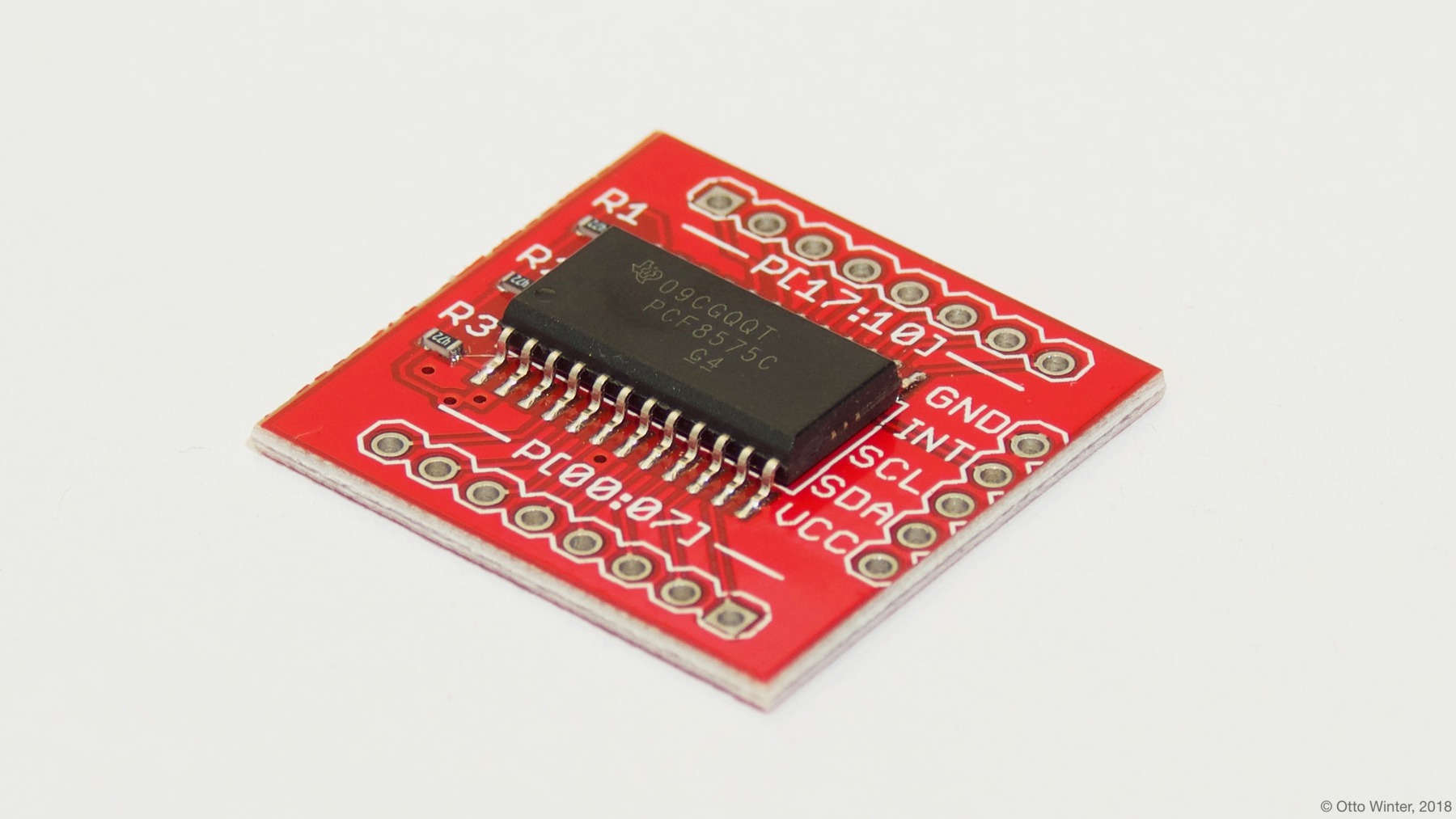
The PCF8574 component allows you to use PCF8574 or PCF8575 I/O expanders (datasheet, SparkFun) in ESPHome. It uses I²C Bus for communication.
Once configured, you can use any of the 8 pins (PCF8574) or 16 pins (PCF8575) as pins for your projects. Within ESPHome they emulate a real internal GPIO pin and can therefore be used with many of ESPHome’s components such as the GPIO binary sensor or GPIO switch.
Any option accepting a Pin Schema can theoretically be used, but some more complicated components that do communication through this I/O expander will not work.

# Example configuration entry
pcf8574:
  - id: 'pcf8574_hub'
    address: 0x21
    pcf8575: false

# Individual outputs
switch:
  - platform: gpio
    name: "PCF8574 Pin #0"
    pin:
      pcf8574: pcf8574_hub
      # Use pin number 0
      number: 0
      # One of INPUT or OUTPUT
      mode:
        output: true
      inverted: false
Configuration variables
id (Required, ID): The id to use for this PCF8574 component.
address (Optional, int): The I²C address of the driver. Defaults to
0x21.pcf8575 (Optional, boolean): Whether this is a 16-pin PCF8575. Defaults to
false.
ℹ️ Note
If you use PCF8575, pin numbers are from 0 to 15, not 0 to 7 and 10 to 17 as datasheet states!
Pin configuration variables
pcf8574 (Required, ID): The id of the PCF8574 component of the pin.
number (Required, int): The pin number.
inverted (Optional, boolean): If all read and written values should be treated as inverted. Defaults to
false.mode (Optional, string): A pin mode to set for the pin at. One of
INPUTorOUTPUT.

