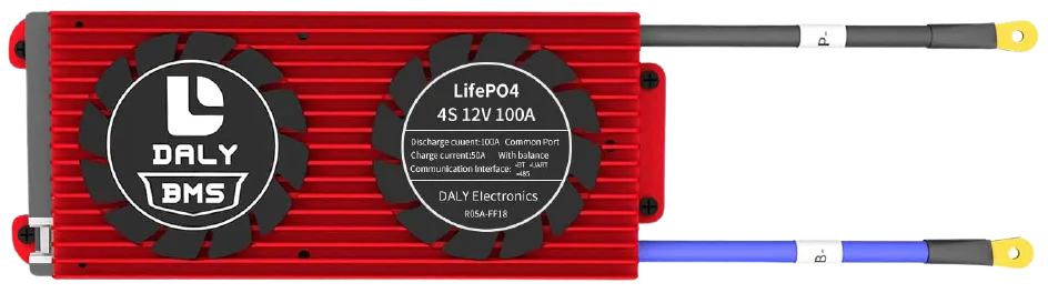
Daly BMS Sensor
The daly_bms sensor platform allows you to use a Daly Smart BMS
(more info)
with ESPHome.
The BMS communicates via UART.
Component/Hub
Section titled “Component/Hub”# Example configuration entrydaly_bms: update_interval: 20sConfiguration variables
Section titled “Configuration variables”- update_interval (Optional, Time): Delay between data requests.
- address (Optional, int): Address to use, defaults to
0x80.
Sensor
Section titled “Sensor”A sensor platform to read BMS data
sensor: - platform: daly_bms voltage: name: "Battery Voltage" current: name: "Battery Current" battery_level: name: "Battery Level" max_cell_voltage: name: "Max Cell Voltage" max_cell_voltage_number: name: "Max Cell Voltage Number" min_cell_voltage: name: "Min Cell Voltage" min_cell_voltage_number: name: "Min Cell Voltage Number" max_temperature: name: "Max Temperature" max_temperature_probe_number: name: "Max Temperature Probe Number" min_temperature: name: "Min Temperature" min_temperature_probe_number: name: "Min Temperature Probe Number" remaining_capacity: name: "Remaining Capacity" cells_number: name: "Cells Number" temperature_1: name: "Temperature 1" temperature_2: name: "Temperature 2" cell_1_voltage: name: "Cell 1 Voltage" cell_2_voltage: name: "Cell 2 Voltage" cell_3_voltage: name: "Cell 3 Voltage" cell_4_voltage: name: "Cell 4 Voltage"Configuration variables
Section titled “Configuration variables”-
voltage (Optional): Voltage of the battery pack connected to Daly BMS. All options from Sensor.
-
current (Optional): Current flowing through the BMS (input or output from battery). All options from Sensor.
-
battery_level (Optional): Battery level in % (SoC). All options from Sensor.
-
max_cell_voltage (Optional): The cell of the battery with the higher voltage. All options from Sensor.
-
max_cell_voltage_number (Optional): The cell number of the battery with the higher voltage. All options from Sensor.
-
min_cell_voltage (Optional): The cell of the battery with the lower voltage. All options from Sensor.
-
min_cell_voltage_number (Optional): The cell number of the battery with the lower voltage. All options from Sensor.
-
max_temperature (Optional): The higher temperature measured from the temperature sensors. All options from Sensor.
-
max_temperature_probe_number (Optional): The sensor number which has measured the higher temperature. All options from Sensor.
-
min_temperature (Optional): The lower temperature measured from the temperature sensors. All options from Sensor.
-
min_temperature_probe_number (Optional): The sensor number which has measured the lower temperature. All options from Sensor.
-
remaining_capacity (Optional): The capacity in Ah left in the battery. All options from Sensor.
-
cells_number (Optional): The number of cells in series in the battery pack. All options from Sensor.
-
temperature_1 (Optional): The first temperature sensor. All options from Sensor.
-
temperature_2 (Optional): The second temperature sensor. All options from Sensor.
-
cell_1_voltage (Optional): The voltage of cell number 1. Cell number can be from 1 to 16. All options from Sensor.
Text Sensor
Section titled “Text Sensor”Text sensor that indicates the status of BMS.
text_sensor: - platform: daly_bms status: name: "BMS Status"Configuration variables
Section titled “Configuration variables”- status (Optional): The BMS Status (Charging, Discharging, Stationary). All options from Text Sensor.
Binary Sensor
Section titled “Binary Sensor”Binary sensor that indicates the status of MOS.
binary_sensor: - platform: daly_bms charging_mos_enabled: name: "Charging MOS" discharging_mos_enabled: name: "Discharging MOS"Configuration variables
Section titled “Configuration variables”-
charging_mos_enabled (Optional): The BMS charging MOS status to enable the recharge of the battery. All options from Binary Sensor.
-
discharging_mos_enabled (Optional): The BMS discharging mos status to enable the load. All options from Binary Sensor.
Control BMS
Section titled “Control BMS”At this moment Daly sensor platform doesn’t support controlling your BMS, but you can make some stuff using uart.write
First you need to setup binary sensors for charging and discharging MOS
binary_sensor: - platform: daly_bms charging_mos_enabled: name: "Daly Charging MOS" id: bin_daly_chg_mos # binary MOS sensor must have ID to use with switch internal: True # but you can make it internal to avoid duplication discharging_mos_enabled: name: "Daly Discharging MOS" id: bin_daly_dischg_mos # binary MOS sensor must have ID to use with switch internal: True # but you can make it internal to avoid duplicationThen you can add switches
switch:  - platform: template    name: "Daly Charging MOS"    lambda: |-      if (id(bin_daly_chg_mos).state) {        return true;      } else {        return false;      }    turn_on_action:      - uart.write:          data: [0xA5, 0x40, 0xDA, 0x08, 0x01, 0x00, 0x00, 0x00, 0x00, 0x00, 0x00, 0x00, 0xC8]      - logger.log:          format: "Send cmd to Daly: Set charge MOS on"    turn_off_action:      - uart.write:          data: [0xA5, 0x40, 0xDA, 0x08, 0x00, 0x00, 0x00, 0x00, 0x00, 0x00, 0x00, 0x00, 0xC7]      - logger.log:          format: "Send cmd to Daly: Set charge MOS off"
  - platform: template    name: "Daly Discharging MOS"    lambda: |-      if (id(bin_daly_dischg_mos).state) {        return true;      } else {        return false;      }    turn_on_action:      - uart.write:          data: [0xA5, 0x40, 0xD9, 0x08, 0x01, 0x00, 0x00, 0x00, 0x00, 0x00, 0x00, 0x00, 0xC7]      - logger.log:          format: "Send cmd to Daly: Set discharge MOS on"    turn_off_action:      - uart.write:          data: [0xA5, 0x40, 0xD9, 0x08, 0x00, 0x00, 0x00, 0x00, 0x00, 0x00, 0x00, 0x00, 0xC6]      - logger.log:          format: "Send cmd to Daly: Set discharge MOS off"
Also you can add select to change battery level
select: - platform: template name: "Daly Battery Level setup" optimistic: True options: - 100% - 75% - 50% - 25% - 0% initial_option: 100% set_action: then: - if: condition: lambda: 'return x == "100%";' then: - uart.write: data: [0xA5, 0x40, 0x21, 0x08, 0x00, 0x00, 0x00, 0x00, 0x00, 0x00, 0x03, 0xE8, 0xF9] - logger.log: format: "Send cmd to Daly: Set SOC to 100%" else: - if: condition: lambda: 'return x == "75%";' then: - uart.write: data: [0xA5, 0x40, 0x21, 0x08, 0x00, 0x00, 0x00, 0x00, 0x00, 0x00, 0x02, 0xEE, 0xFE] - logger.log: format: "Send cmd to Daly: Set SOC to 75%" else: - if: condition: lambda: 'return x == "50%";' then: - uart.write: data: [0xA5, 0x40, 0x21, 0x08, 0x00, 0x00, 0x00, 0x00, 0x00, 0x00, 0x01, 0xF4, 0x03] - logger.log: format: "Send cmd to Daly: Set SOC to 50%" else: - if: condition: lambda: 'return x == "25%";' then: - uart.write: data: [0xA5, 0x40, 0x21, 0x08, 0x00, 0x00, 0x00, 0x00, 0x00, 0x00, 0x00, 0xFA, 0x08] - logger.log: format: "Send cmd to Daly: Set SOC to 25%" else: - if: condition: lambda: 'return x == "0%";' then: - uart.write: data: [0xA5, 0x40, 0x21, 0x08, 0x00, 0x00, 0x00, 0x00, 0x00, 0x00, 0x00, 0x00, 0x0E] - logger.log: format: "Send cmd to Daly: Set SOC to 0%"UART Connection
Section titled “UART Connection”Connect RX from BMS to TX in ESP board and TX from BMS to RX in ESP board
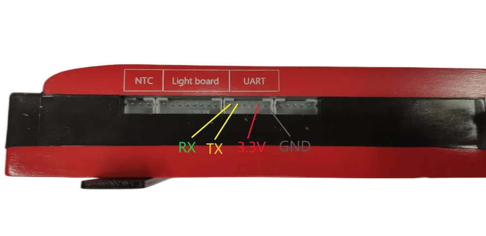
3.3v Warning: some BMS 3.3v cant source large currents and may not work to properly power the ESP. If you are having WIFI connection issues or similar, try a different power source. There is 12-15v available on the Daly connector which via a proper step-down converter can properly power the ESP.
On the ESP32 (untested on ESP8266) if you are having missing data (such as Temperature 1/2), it may be due to UART buffer size. Add the following to your configuration to increase the buffer from the default 256 to 512.
uart: ... rx_buffer_size: 512