Resistance Sensor
The resistance platform is a helper sensor that allows you to convert readings
from a voltage sensor (such as the ADC Sensor) into resistance readings
in Ω (ohm).
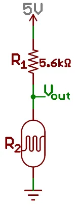
In order to calculate the resistance, the circuit needs to be set up in a voltage divider circuit. This consists of three parts:
-
A voltage reference, usually this is connected to 3.3V (VCC). For example in the image below it is 5V (though on ESPs you should not use that voltage)
-
A reference resistor with constant resistance. For example below it is R₁ with a value of 5.6kOhm.
-
The variable resistor we wish the read the resistance of. Here R₂.
There are two kinds of configurations for this circuit: Either the variable resistor is close to GND (DOWNSTREAM) or it is closer to VCC (UPSTREAM).
# Example configuration entrysensor:  - platform: resistance    sensor: source_sensor    configuration: DOWNSTREAM    resistor: 5.6kOhm    name: Resistance Sensor
# Example source sensor: - platform: adc id: source_sensor pin: A0Some boards like NodeMCUv2 needs to multiply ADC reading by 3.3 to provide accurate result because they have built-in voltage divider on ADC pin (https://arduino.stackexchange.com/a/71952)
# Example source sensor: - platform: adc id: source_sensor pin: A0 filters: - multiply: 3.3Configuration variables
Section titled “Configuration variables”-
sensor (Required, ID): The sensor to read the voltage values from to convert to resistance readings.
-
configuration (Required, string): The type of circuit, one of
DOWNSTREAMorUPSTREAM. -
resistor (Required, float): The value of the resistor with a constant value.
-
reference_voltage (Optional, float): The reference voltage. Defaults to
3.3V. -
All other options from Sensor.