Physically Connecting to your Device
The most difficult part of setting up a new ESPHome device is the initial installation, which requires connecting your ESP device to a computer using a data cable.
You only need to do this once per device. Once you've flashed ESPHome on a device, you can use Ota to upload new versions or configuration changes wirelessly.
ESPHome runs on a wide variety of devices, so it's hard to list any specific set of tools that you need or to give instructions on how to connect. This guide tries to cover some of the more common flashing situations. If your device doesn't fit any of these situations, try and find a guide for your specific device in the devices guides or elsewhere on the internet.
Connecting to the ESP
Section titled “Connecting to the ESP”There's a wide variety of situations you might find yourself in, each of which requires you do something different to connect your computer to the ESP in order to flash it.
You only need to physically connect to it once. Once you've flashed your device and connected it to your WiFi, you can use Ota to install software remotely.
Programming a ESP-based device is done by connecting the serial port on the ESP8266/ESP32 to your computer through a USB to serial adapter. Some devices have adapter built into the circuit board (and some even have the programmer embedded in the MCU, in which case things are a bit easier.
In case you use an external serial programmer connected to RX and TX of the ESP, choose one based on CH340 as it's the most reliable and the cheapest one to use for flashing. Programmers based on CP2102 or PL2303 are compatible with many devices, but using an external 3.3V supply might be necessary for them.
Plug in the board or the serial programmer into a free USB port and check if it has been properly detected
by your computer. The firmware programming tools use a serial interface to communicate with your device.
On Windows these interfaces are named COM1, COM2, etc. and on Linux they are named /dev/ttyUSB0,
/dev/ttyACM1, etc.
NOTE
If it's not showing up as a serial port, you might not have the required drivers installed. The model number you need is engraved on the chip connected to the USB port. ESPs and programmers usually ship with one of these UART chips:
With the exception of the situation where you have a USB port, you need to make five electrical connections to program an ESP-based board:
+3.3V, or occasionally+5.0VGND, or groundTXof programmer toRXof theESPRXof programmer toTXof theESPIO0, used to place the board into programming mode. This is often a button that you need to hold down while connecting the power (+3.3V).
The power supplied to the device is one of the most important elements for both flashing
the device and for stable operation. You must ensure that the device receives sufficient
power (current AND appropriate voltage level) to properly flash the firmware on the device.
When using an external 3.3V supply, ensure the ground (GND ) of both are connected together,
this ensures a common ground. A PC power supply can be a good source for 3.3V DC power.
NOTE
Some adapters can be switched between 3.3V and 5V for the data pins, but still provide 5V on the power pin which
will irreparably destroy your device. You MUST make sure the data (RX and TX ) and VCC pins are
set for 3.3V.
ESP needs to be put into programming mode or flash mode before the firmware can be uploaded. This is
done by connecting GPIO0 pin to GND while the chip is booting.
To put the ESP into programming mode:
- Disconnect the USB connection of your board or serial programmer from the computer (to power off your ESP)
- Bridge
GPIO0andGND(by pressing the on-board button or connection with a wire) - Connect the board or serial programmer to your computer (ensuring ESP powers up)
- After a few seconds disconnect
GPIO0fromGND(release button or remove the wire connection). On devices that do not provide theGPIO0connected button, it may be easier to leave the wired bridge in place throughout the entire flashing process (erase & upload). Doing so will not create any problems. After the firmware is uploaded successfully, remove the bridge. This allows the device to boot normally.
You may need to power-cycle the ESP between erasing and uploading the firmware, this can be done by disconnecting and
reconnecting, of course with GPIO0 and GND still connected to each other.
RX and TX can be sometimes swapped. If programming your board doesn't work the
first time, try flipping the wires connected to those pins before trying again.

WARNING
Do not connect your device to mains electricity while following this guide. If your device is open and plugged directly into the wall, you'll be a single touch away from being electrocuted.
Note that this does not apply if your device uses a separate "wall wart" or a power brick. Using an external power supply while flashing is an advanced topic not covered here, but does not pose any safety risk.
You are solely responsible for your own safety. If you feel something is wrong or are uncomfortable with continuing, stop immediately.
USB Port on Device
Section titled “USB Port on Device”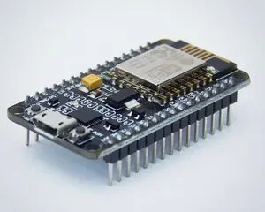
Development boards often come with a USB port built in. This USB port is connected to a serial adapter, so you don't need a separate serial adapter. You can use just a USB data cable to connect it to your computer to program it. Additionally, a development board can also be used to flash other ESPs. Read more here.
This isn't likely to be very useful without connecting additional sensors to it by either soldering or using a breadboard, but you do not need anything else to just flash ESPHome on it.
Pre-soldered Programming Header
Section titled “Pre-soldered Programming Header”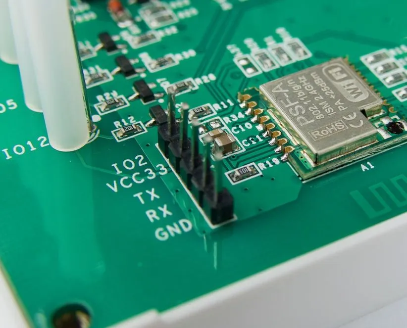
In this situation, you'll need just jumper wires and a USB to serial adapter. You don't need to solder anything, that's already been done by the factory.
Unpopulated Programming Header
Section titled “Unpopulated Programming Header”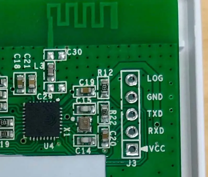
You can probably get away with jumper wires and a USB to serial adapter. You can place the male end of the wires directly into the circuit board and hold them into place with your hand until you're done flashing the board.
These headers sometimes have writing on the circuit board indicating what each pin is. If your header does not, either look it up on the internet, or use a multimeter in continuity mode to figure it out (advanced topic).
Solder-filled Programming Header
Section titled “Solder-filled Programming Header”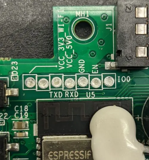
You'll need a USB to serial adapter, jumper wires, a soldering iron, and probably solder and some breakaway headers if your board looks like this.
You can try placing the jumper wires in the right place, but you'll have trouble holding them without having them slide around. You'll want to solder a header onto the programming port in this situation.
These headers sometimes have writing on the circuit board indicating what each pin is. If your header does not, either look it up on the internet, or use a multimeter in continuity mode to figure it out (advanced topic).
Module Only
Section titled “Module Only”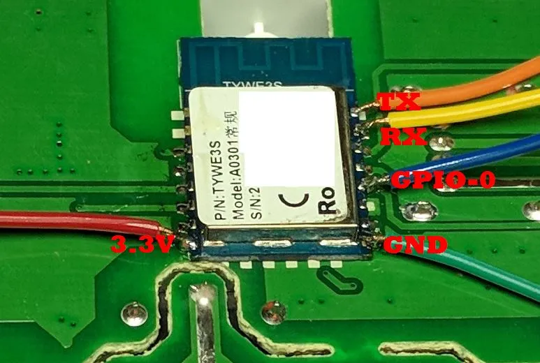
If the device has a module but no programming headers, things get a bit tricky. You'll need a USB to serial adapter, jumper wires, wire strippers, wire snips, a soldering iron, solder, and a bit of flux would help.
Cut the jumper wires, strip a bit off the end, and then solder them onto the module. You can find the correct places to solder the wires by looking up the module model number on the internet. You can find one list of commonly usedmodules here.
Bare Chip
Section titled “Bare Chip”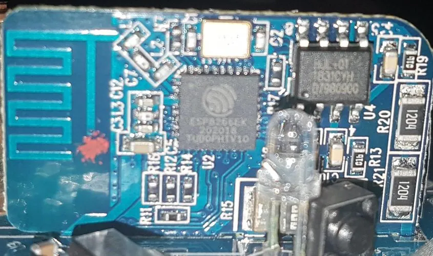
This is an advanced topic and won't be covered in detail, but you have three options:
-
You can hope that your device is supported by an OTA conversation tool. Most these tools have been broken by vendors, and the ESPHome community can't help you with using these tools.
-
If the programming wires connect to a larger component like a resistor, you can solder or clip your jumper wires to that larger component.
-
You can use your amazing microsoldering skills to connect directly to the IC.
Materials
Section titled “Materials”Because we're working with hardware, we might need some additional tools, depending on the situation. Already have all this stuff? You're good to go!
But if you don't, don't go out and buy everything just yet. Read through the guide first and make a list of everything you need. Different situations will require different parts and tools.
| Name | Purpose | Approx. cost | Picture |
|---|---|---|---|
| USB to micro-USB/mini-USB/USB-C | If your target device has a USB port on it, you need the appropriate data cable to connect to it. A power only USB cable that usually comes presupplied with powerbanks won't work. | 10 | 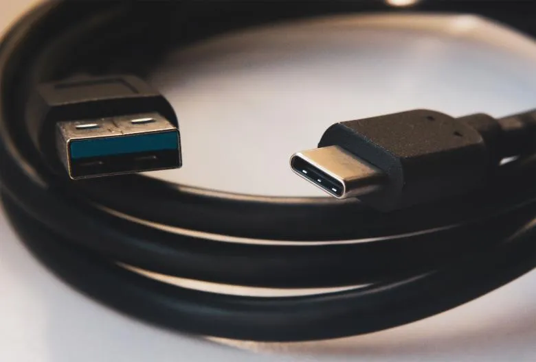 |
| USB to serial adapter | Serial communication is a simple way of talking to other devices, like the ESP32/ESP8266 you're flashing. But your computer probably doesn't have this capability built-in. "Serial", "UART", "TTL", and "COM" are all more-or-less synonyms. There are many different types of these, so don't worry if yours doesn't look exactly like the picture. However, you do need one with a voltage regulator. The Tasmota website provides a good set of suggestions on what to buy. Any ESP development board with functioning USB_UART bridge chip can also be used instead. | 10 | 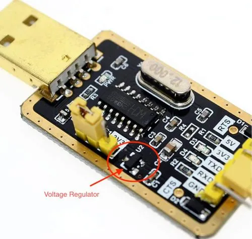 |
| Jumper wires | Used to connect two things together electrically. The male end has metal protuding and is plugged into the female end of a wire or board. They come in varying lengths too, but for our purposes, any length will do. | 8 for a pack | 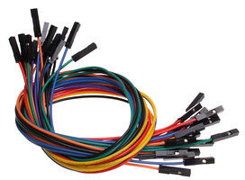 |
| Breakable headers | Soldered to a PCB to provide a way to connect jumper wires. The distance between the metal pins is known as the pitch, and is usually 2.54mm for what we're doing. This sort of header can be cut to the correct length along the groves. | 8 for a pack | 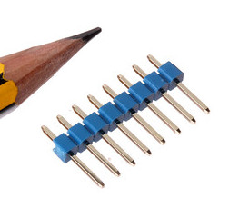 |
| Wire snips, wire cutters, flush cutters | Used to cut wire. These can often be subsituted by a knife or scissors, but be careful not to hurt yourself. | 15 | 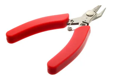 |
| Wire strippers | Used to remove the insulation from wires, leaving the conductive metal interior exposed. These can often be subsituted by a knife, scissors, or fingernails, but be careful not to hurt yourself. There are many different styles, not just that in the picture. You'll want something that works with fairly thin wire, about 20 AWG to 26 AWG. | 15 | 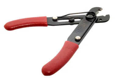 |
| Soldering iron | Used to melt metal, called solder, to connect things together in an electrically conductive way. You'll want something with temperature control. Other than that, there are many varying opinions and options here. The /r/AskElectronics wiki has some good suggestions. The following would serve you well, although be careful to buy from a reliable source: - Hakko FX-888D - KSGER T12 - TS100/TS80 | 120 | 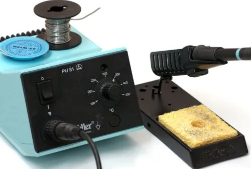 |
| Electronics solder | Molten metal used to join things in an electrically conductive way. There are two types, leaded and lead-free. Leaded melts at a lower temperature and is a little easier to work with, but is hazardous to the environment (but not to humans in this form). Electronics solder also usually has a "rosin core", which helps clean the surfaces to allow the solder to stick. You absolutely do not want plumbing solder, also known as "acid core" or "silver solder". It needs much higher temperatures than we can safely use here. | 12 | 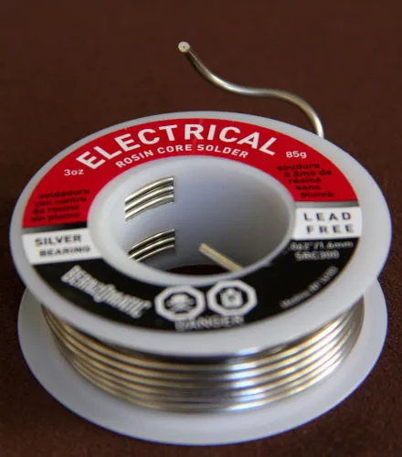 |
| Electronics flux | Used to clean the metal surfaces before soldering them together. Sometimes the rosin core of the solder doesn't provide enough, so you'd want add some extra. This stuff is helpful, but probably not needed for this guide since we won't be doing any advanced soldering. If you do buy it, you absolutely do not want plumber's flux. It will destroy your circuit boards. | 12 | 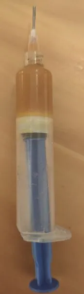 |